

| BreadBoard | |
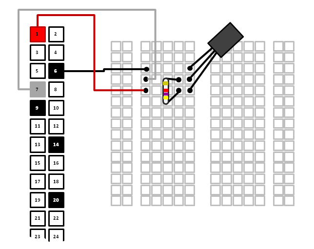
| A DS18B20 Temperature Sensor x1 | |
| 4.7KOhms resistor x1 | |
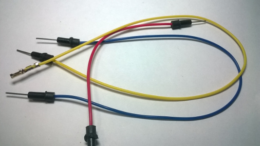
| Male-Female jumper wires | |
$ sudo nano /boot/config.txtopen the /boot/config.txt file for editing. Then scroll down to the bottom of the file, and add the line:
dtoverlay=w1-gpio
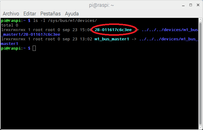
$ ls -l /sys/bus/w1/devices/to see a list of the devices currently connected to your Raspberry Pi. Your temperature sensor will appear with an address in the format 28-xxxxxxxxxxx. Below you can see that our temperature sensor address was 28-011617c6c3ee. Each DS18B20 temperature sensor has a unique hard-coded address so that you can connect up multiple temperature sensors when required and still read them individually.
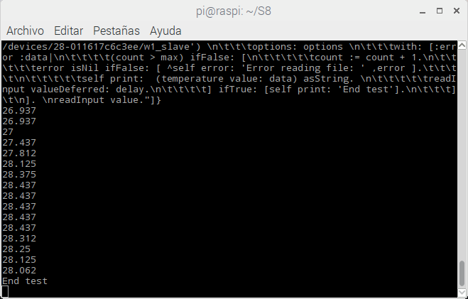
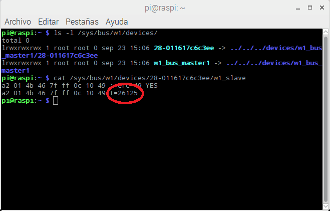
$ cat /sys/bus/w1/devices/28-011617c6c3ee/w1_slave
take note of the server address e.g. SystemServer running at http://192.168.1.???:8088$ sudo node n8.snapshot.js
| delay count max readInput options temperature |
delay := 100.
count := 0.
max   := 15.
options := ((#encoding -> #utf8),(#flag -> #r)).

temperature := [:data|
	| parts temp |
	data isEmpty ifTrue:[ data ] ifFalse: [
		parts := data asArrayOfSubstringsSeparatedBy: String lf.
		parts := (parts at:2) asArrayOfSubstringsSeparatedBy: $=.
		temp := ((parts at:2) asNumber) / 1000.
		temp.
	]
].

readInput := [
		NodeJS fs
			readFile: ('/sys/bus/w1/devices/28-011617c6c3ee/w1_slave')
			options: options
			with: [:error :data|
				(count > max) ifFalse: [
					count := count + 1.
					error isNil ifFalse: [ ^self error: 'Error reading file: ' ,error ].
					self print:  (temperature value: data) asString.
					readInput valueDeferred: delay.
				] ifTrue: [self print: 'End test'].
			]
].
readInput value.